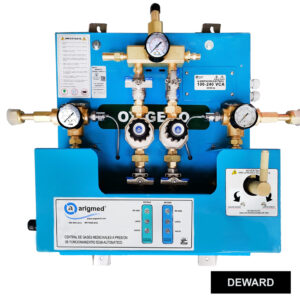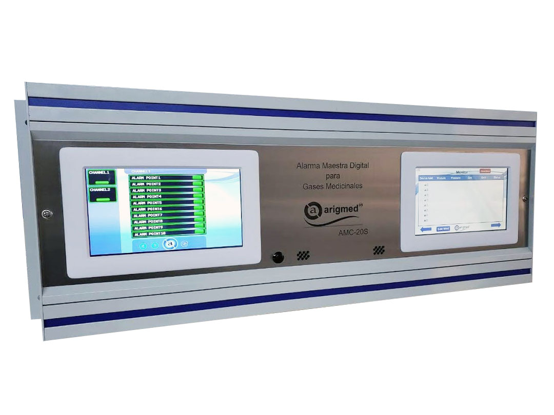

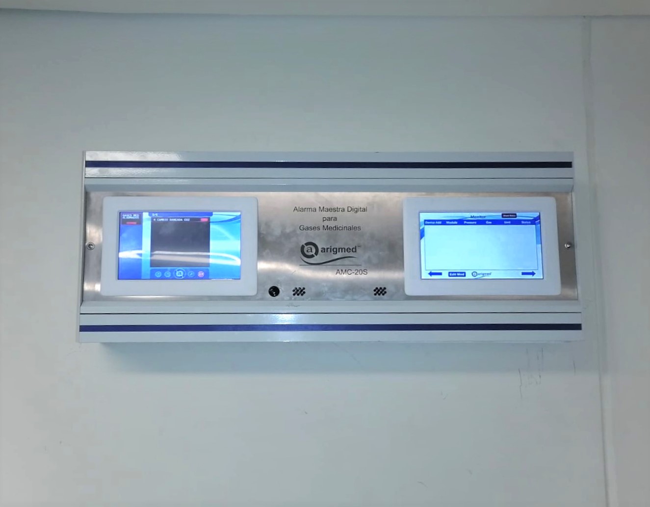
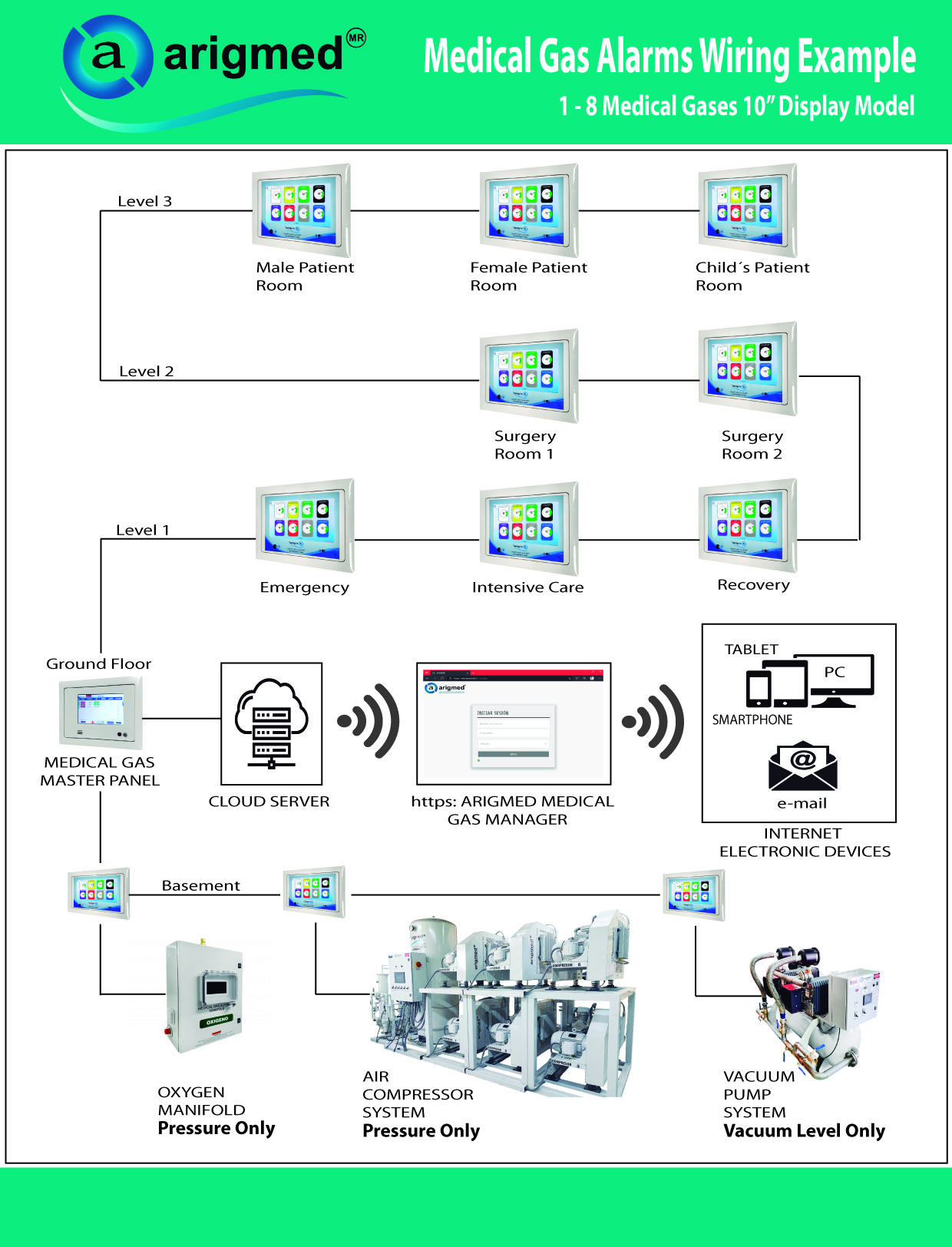
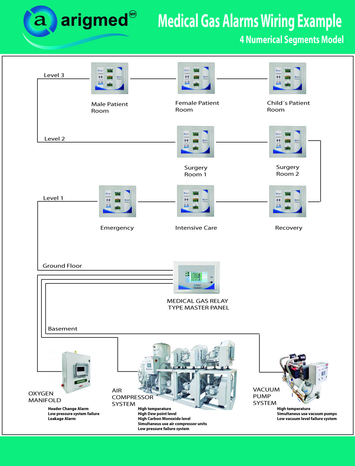

Medical Gas Combination Master Panel
![]()
*To a quote contact our technical and sales advisors. Your information must be valid and true (name, full address, email, phone number, country, postal code, I.D. tax status).
*We always require clear specifications in order to make a formal quote.

- Description
- Digital Relay Master Alarm Specifications
- Digital Master Alarm Specifications
- Brochure
- Legal Notice
Description
Combined Alarm (digital relay master alarm + digital series 2 master alarm), includes:
- One digital-type relay system master alarm.
- One digital-type series 2 master alarm.
- Compliant with NFPA99 standard.
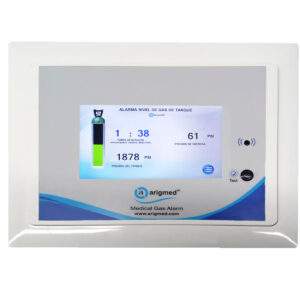
Digital Relay Master Alarm Specifications
⚙️ Technical Specifications. 🔧 Enclosure:- From 10 to 60 signals in an enclosure made from special-extrusion aluminum profiles, alloy 6063 temper 5, with electrostatic powder coating baked finish.
- Wall-mounted installation only.
- Modules of 10 signals with a maximum capacity of 60 signals per relay signal master alarm panel, Series 2 model (minimum 10 signals, maximum 60).
- To handle more than 60 signals, two screens or alarms are required.
-
- Flashing alarms per signal indicating an “abnormal” condition.
- “Normal” condition per signal (no alarm event).
- Signal name display on the 7″ touchscreen.
-
-
-
- Real-time detection of “abnormal” events from any equipment or alarm connected via relay communication technology (dry contacts).
-
-
-
-
-
- Modules of 10 relay port signals (dry contacts) for data output, with a maximum of 40 signals in multiples of 10.
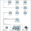
- RS485 communication protocol via SERIAL connection for linking to zone alarm groups or to equipment using relay communication technology (dry contacts).
-
-
-
-
-
- Edit signal name.
- Recommended for integration with medical gas supply centers (cylinder banks, cryogenic tanks, and oxygen generators).
- Recommended for integration with medical-grade air compressors and vacuum pumps.
-
-
-
-
-
- Display button to mute alarm sound (auto reset after 1 hour if pressure does not normalize).
- System test button on display.
-
-
-
-
-
- Protected document, exclusive to the brand’s equipment.
- Request via email and form located in the manuals and after-sales service section.
-
-
-
-
-
- Flush-mount box for electrical and data connections.
- Belden STP #8461ZH or #8208 cable for additional relay port (point-to-point connection, no splices for relay system).
- Power supply: 110–220V, 50–60 Hz.
-
-
-
-
-
- Voltage fluctuations in the electrical supply.
- Use of emergency power plants as main source.
- Intermittent or unstable power supply.
- Frequent power outages with repeated activation of emergency power plant.
-
-
-
-
- Verify physical grounding connection.
- Install an electrical backup system (No-Break).
- Install surge suppressor for protection against electrical discharges.
-
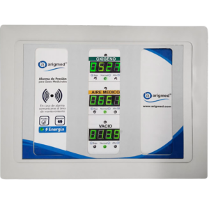
Digital Master Alarm Specifications
⚙️ Technical Specifications. 🔧 Enclosure:- Manufactured from special extrusion aluminum profiles, alloy 6063 temper 5, with baked electrostatic powder coating finish.
- Wall-mounted installation only.
- Supports up to 127 medical surgical gas or vacuum sensors simultaneously.
-
- Real-time display of Pressure and Vacuum readings from each zone alarm connected to the Series 2 master alarm panel.
- NFPA99 Color Option and Gas Nomenclature for each medical gas alarm connected to the Series 2 master alarm panel.
- ISO Color Option and Gas Nomenclature for each medical gas alarm connected to the Series 2 master alarm panel.
- Flashing Alarms on each Gas Module for each zone alarm connected to the Series 2 master alarm panel.
- Display of the area name where each zone alarm is located and connected to the Series 2 master alarm panel.
-
-
-
- Alarm for detecting high and low pressure events in real time.
-
-
-
-
-
- RJ45 Female Ports for data input and output.
- 1 relay port (dry contacts) for data output.
- RS485 communication protocol via SERIAL connection for linking to zone alarm groups and to Arigmed’s ethernet interface (Internet).
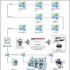
- INTRANET connection via ARIGMED ETHERNET INTERFACE, with HTML link for system visualization on remote devices such as PC, TABLET, SMARTPHONE via website.
-
-
-
-
-
- Edit the name of the area where the zone alarm will be located.
- Generate alarm event reports for the entire system in exportable files in PDF (Acrobat Reader) and XLS (Excel) format, with 30-day storage time in the system.
-
-
-
-
-
- Protected document, exclusive to the brand’s equipment.
- Request via email and form located in the manuals and after-sales service section.
-
-
-
-
-
- Wall-mounted box for electrical and data cable block connections.
- Power input 110–220VAC 50/60 Hz.
- Data network with CAT6 UTP (unshielded twisted pair) cable in SERIAL connection with 10″ display zone alarm groups.
- HTML hosting for Arigmed medical gas system administrator (may incur additional user costs).
- Arigmed ethernet interface for Arigmed website HTML monitoring of remote pressure systems.
- User system hosting on ARIGMED monitoring website may generate additional charges.
- User may receive “real-time” email notification with the alarm event triggered in the medical gas system.
- Fixed Internet access with good strength and quality.
-
-
-
-
-
- Voltage fluctuations in the electrical supply.
- Use of emergency power plants as main source.
- Intermittent or unstable power supply.
- Frequent power outages with repeated activation of emergency power plant.
-
-
-
-
- Verify physical grounding connection.
- Install electrical backup system (No-Break).
- Install surge suppressor for protection against electrical discharges.
-
Brochure
Download:No Available
Legal Notice
Intellectual and industrial property: All rights reserved.- All access to this website is subject to the following conditions: The reproduction, permanent storage and dissemination of the contents or any other use that has a public or commercial purpose is forbidden without prior written notice and approval of Grupo Arigmed S. de R.L. de C.V.
- All documents, images and contents, on this website are from the Intellectual property of Grupo Arigmed S. de R.L. de C.V., any type of copy, plagiarism or similarity in those (documents, images and contents), will be object of legal actions to avoid its use by unauthorized persons, organizations or companies, as well to compensate author´s damage caused.